Description
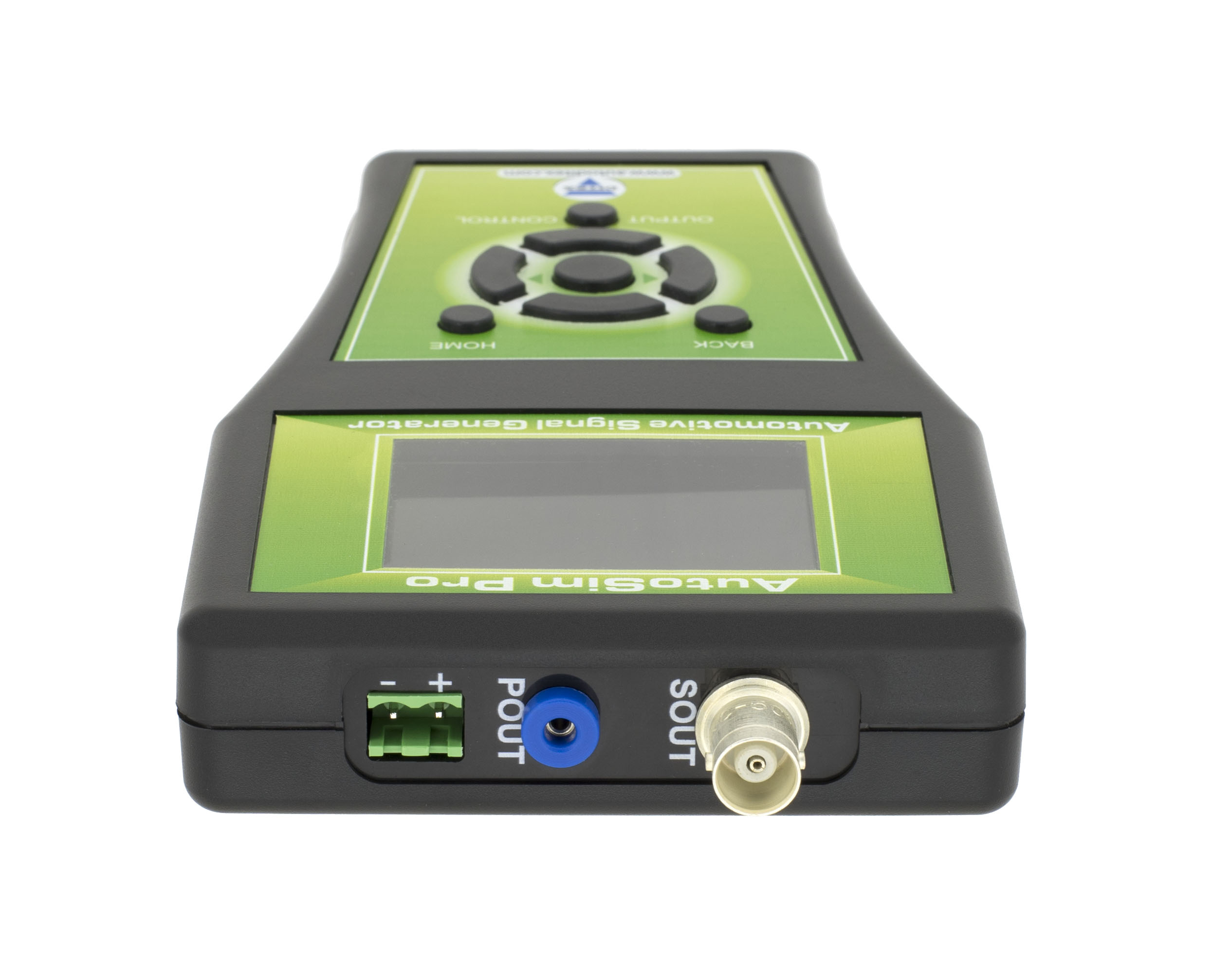
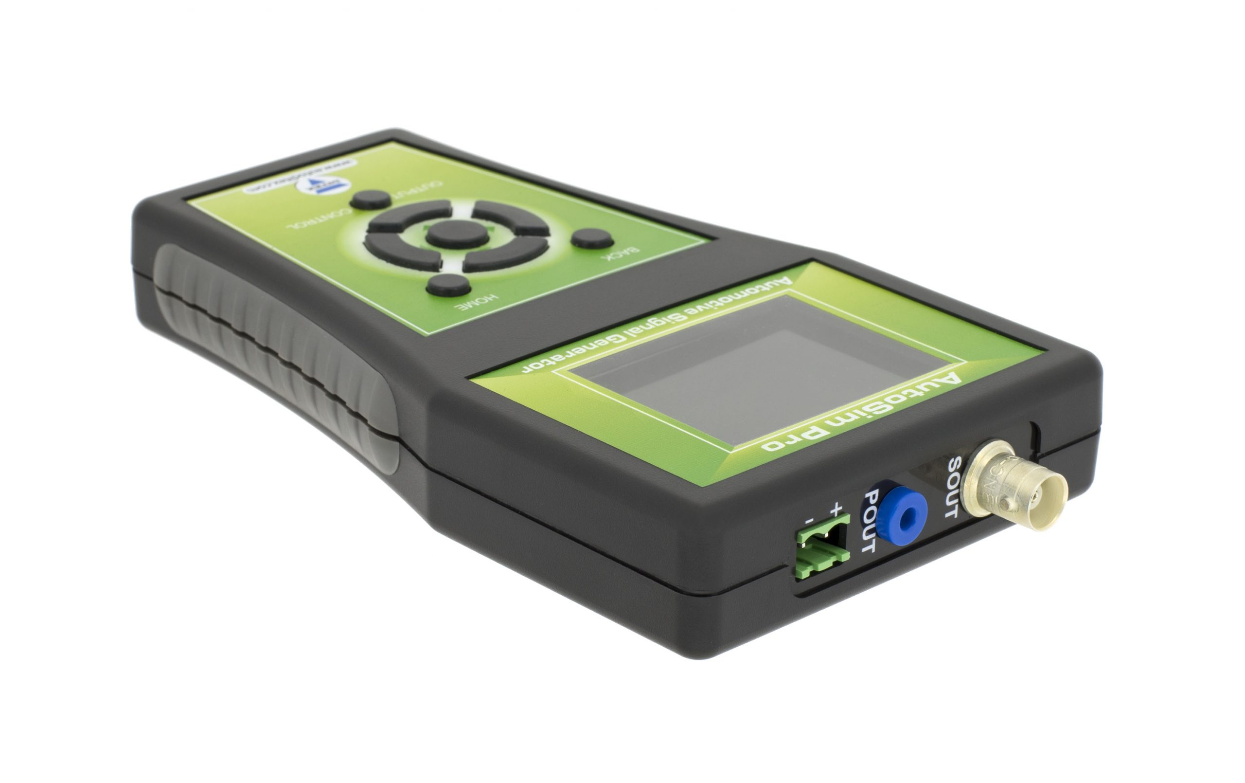
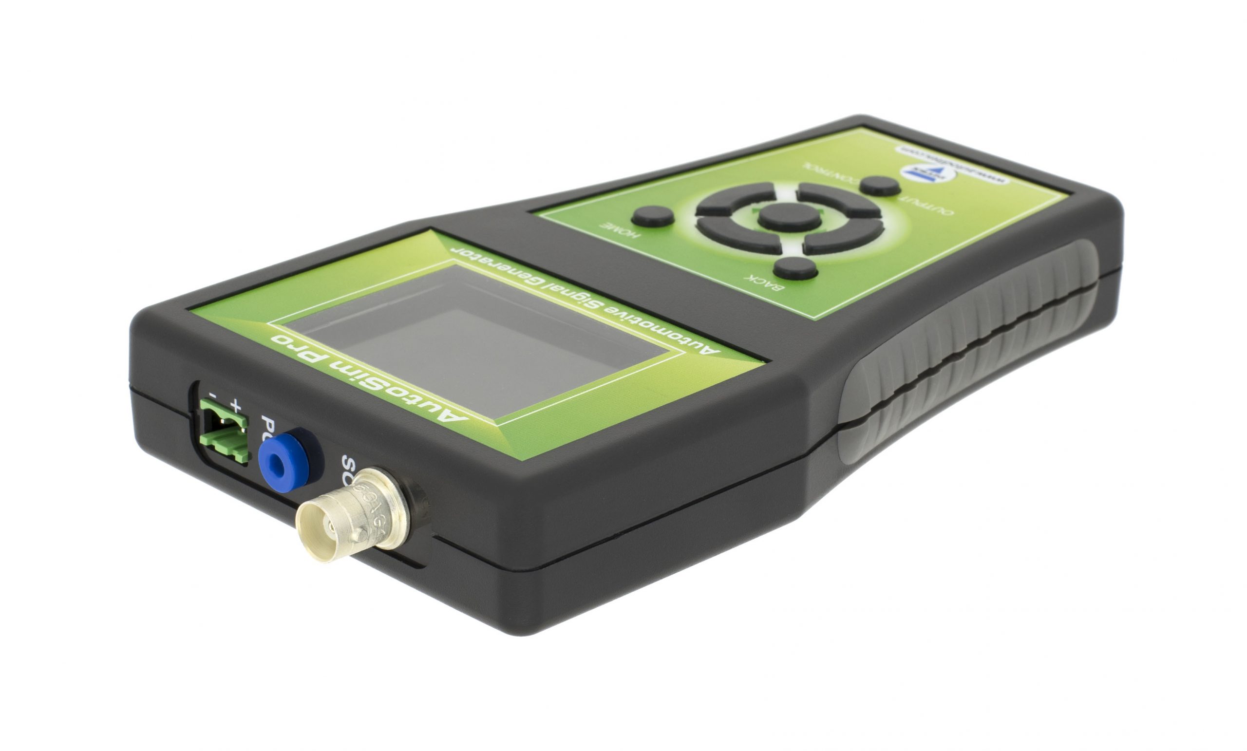
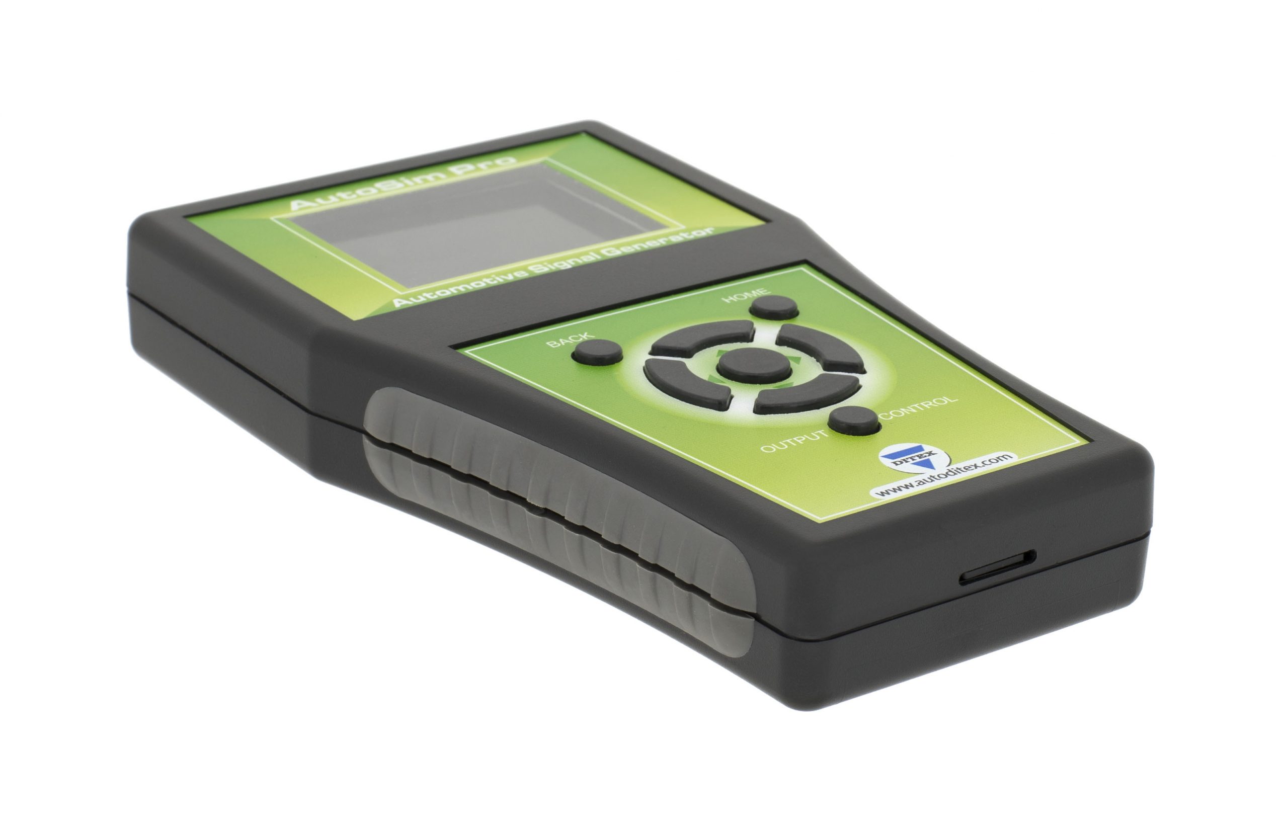
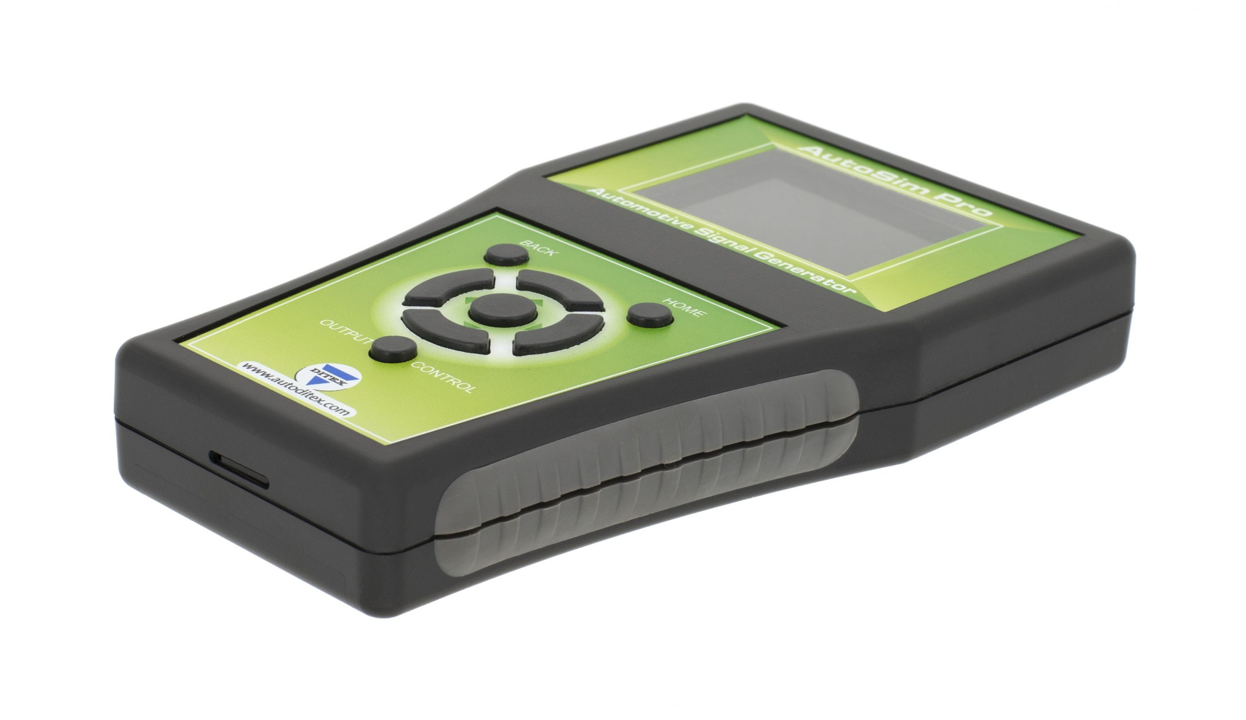
Since its release in 2012, the AutoSim Pro sensor simulator has proven itself extremely popular with both technicians and professional diagnosticians, thanks to its friendly user interface and reliable operation.
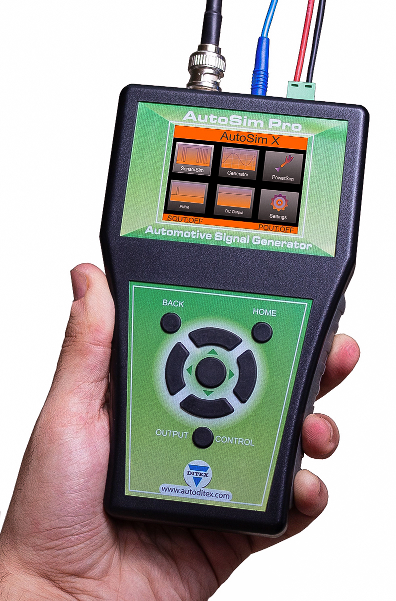
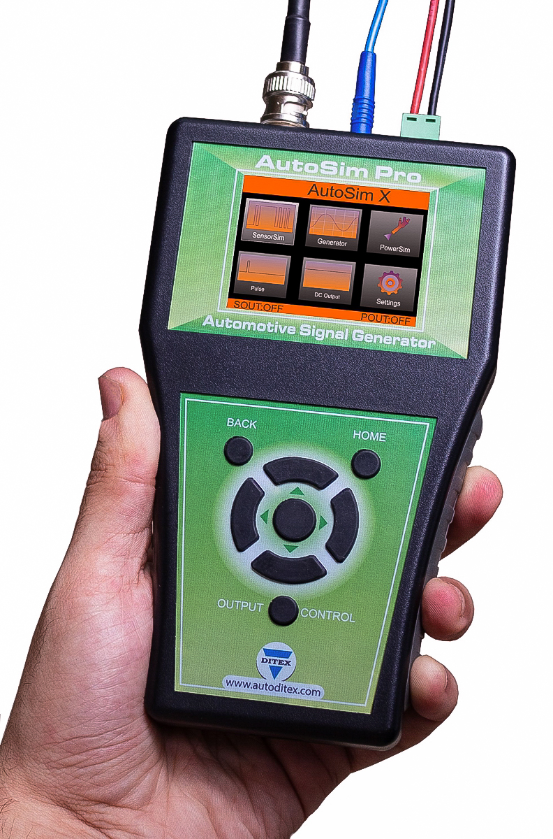
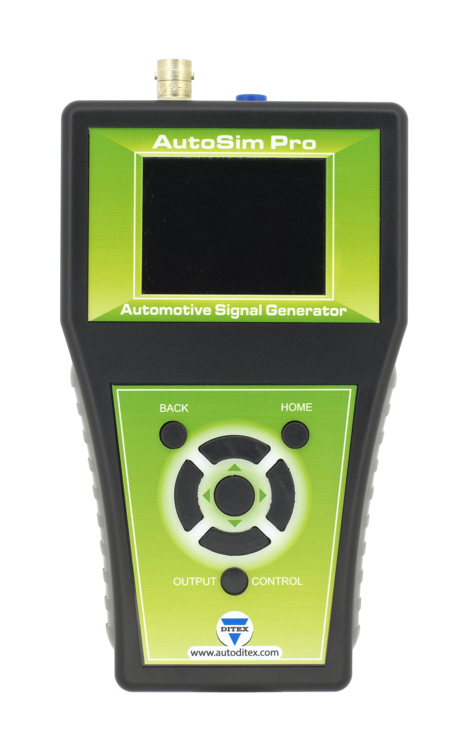
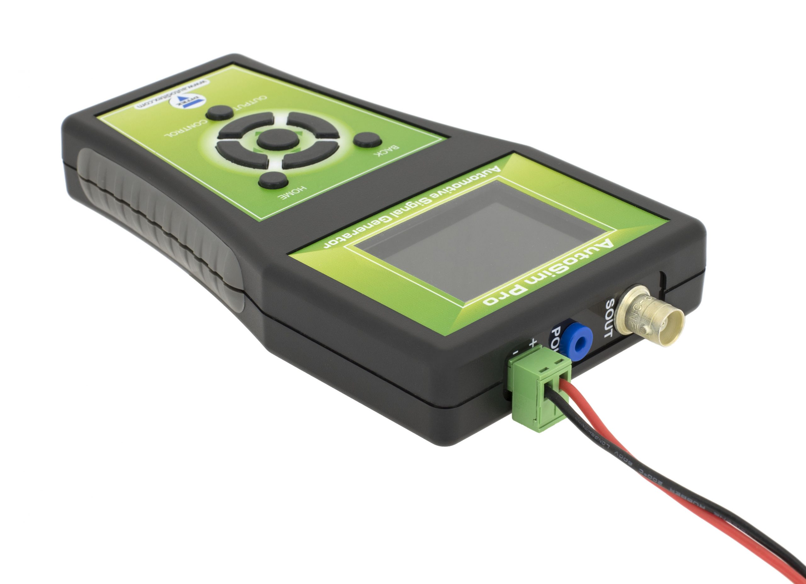
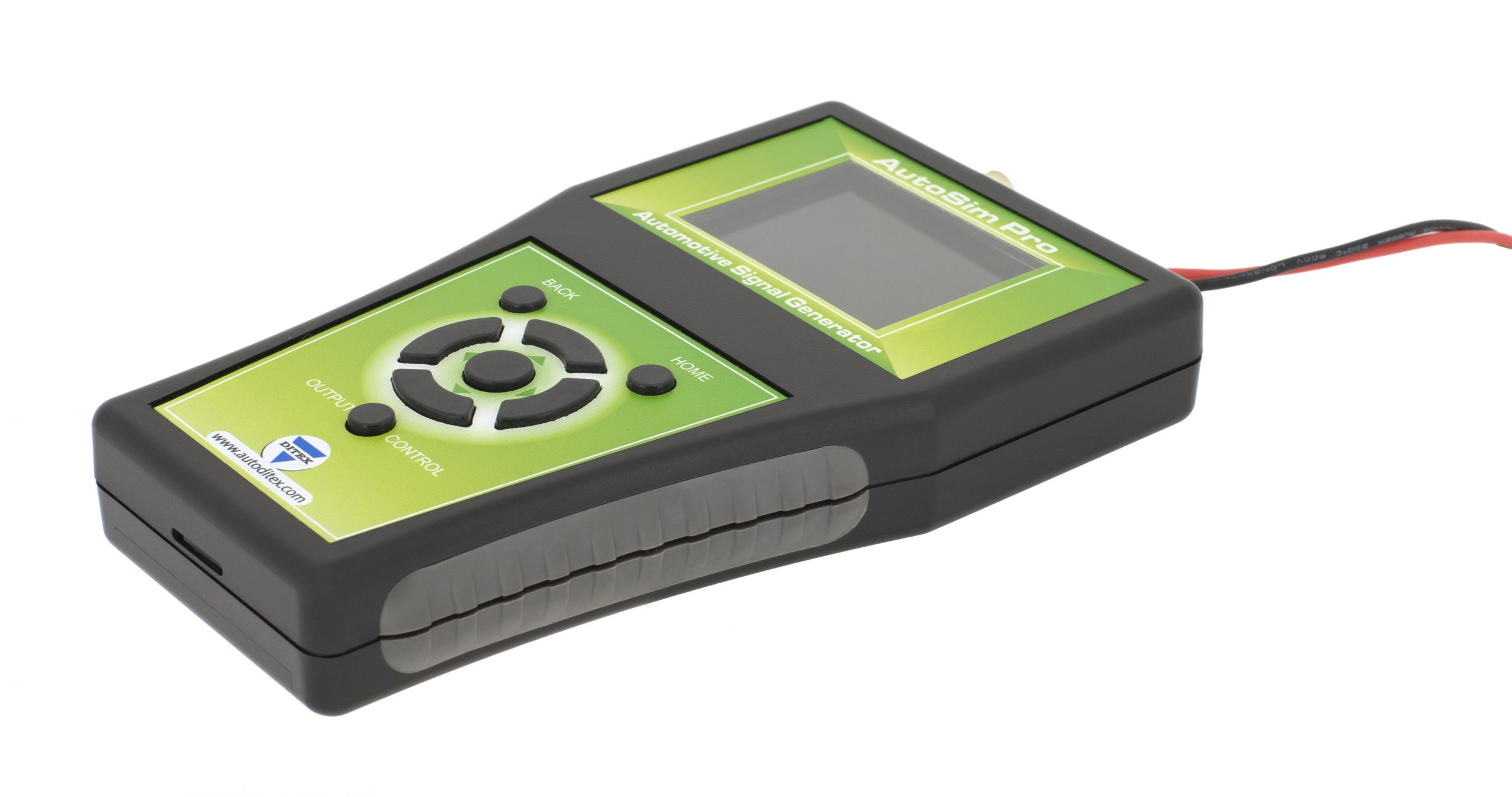
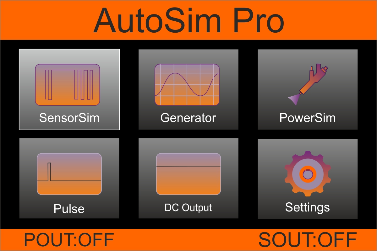
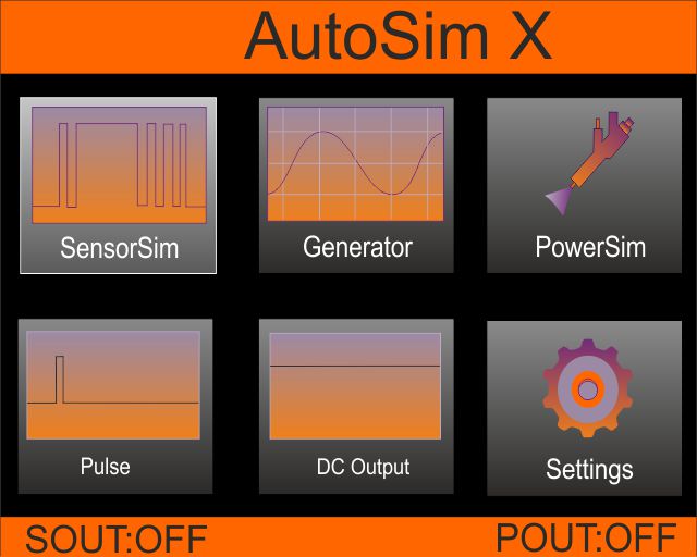
In general, the AutoSim Pro is a specialized signal generator for testing sensors. With this tool, it is possible to tell whether an ECU, a feed, a plug-in connection, or a sensor is defective. This allows for efficient fault elimination without replacing parts “on suspicion”. One of the special features of this device is that it has easy and intuitive operation via function keys. The display continuously shows the most important settings such as current waveform, frequency, amplitude, offset, ramp time and pulse width.
MULTI-PURPOSE AUTOMOTIVE SIMULATOR
Signal generator
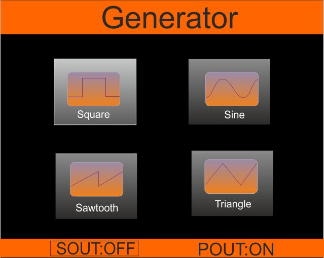
The AutoSim Pro provides the most prevalent signals on a vehicle today; including sine and square waves up to 20 kHz, which makes the device the ideal companion for experiments with all type of components and sensors, as well as for the analysis of electrical wiring. You have complete control over the output signal: peak-to-peak amplitude, frequency, duty-cycle and pulse width. A microcontroller sets the output voltage in the range of 0V to ±12V accordingly to the programmed curves.
PWM
There is a PWM generator for the dynamic control of vehicle actuators using pulse width modulation. The PWM generator function was specially designed to control flaps, actuators, valves, injectors and smaller DC motors. Generates variable power PWM signal up to 4 A.
Precise DC voltage source
The AutoSim Pro low-noise, high-resolution DC voltage output function is the right choice when a precision source of DC voltage is needed. Its bipolar output delivers up to ±12 V with 10 mV resolution and up to 35 mA of current.
Sensor embedded presets
In addition, there are built-in preset configurations for the simulation of CKP Inductive, CKP Hall Effect, Zirconia Lambda sensors, Titania oxygen sensors and Knock Sensors. As an example, a technician can disconnect sensors and inject the signals into the harness and watch the scope to see if the PCM responds in a “normal” manner.

